FIMMPROPA bi-directional optical propagation tool |
   |
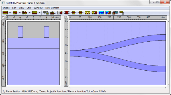
A Planar Optical Y-Junction Power Splitter3D simulation with FIMMPROP softwareFIMMPROP was used to simulate a planar Y-junction power splitter made in GaAs/AlGaAs. The design is shown below. FIMMPROP was able to model this structure with a precision of 0.7% in 34s on a standard desktop computer (full vectorial 3D). It was then able to scan the length of the taper very quickly (1.5s per additional length).
FIMMPROP is a very efficient tool for the simulation and modelling of tapers and slowly varying structures:
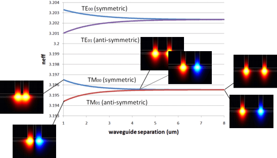
Optimising the Y-Junction gapThe structure is based on a GaAs/AlGaAs planar rib waveguide. The Y-junction was geometrically obtained by superimposing a S-bend with its mirror image. The width of each rib waveguide is 1.5um and gap between the two waveguides at the end was chosen to be 6.5um. The distance between the two output waveguides was optimised by analysing the evolution of the modes of the end section with the gap width. These modes are the fundamental symmetric and anti-symmetric TE-like supermodes of the cross-section. Please note that although these modes appear as supermodes due to the symmetry of the structure, this does not necessarily mean that the waveguides are coupled. The coupling between the two branches can be easily characterised: the strength of the coupling will become negligible as the difference in effective index between these two modes tends to zero. In order to optimise the distance between the two output waveguides, we simply need to vary the gap width and find out when the effective indices become identical. In FIMMPROP, this analysis can be performed automatically in just a few seconds, allowing you to improve dramatically the performance and compactness of your design at a very low cost! An example of such analysis is shown below.
Simulation ResultsThe Y-junction was designed and simulated in 3D with FIMMPROP, the local modes being calculated with the finite-difference FDM Solver. The simulation took 34s on a 4-core i7-2600 CPU. FIMMPROP is able to take advantage of the symmetry of the structure; in this case the entire structure is symmetric with respect to the YZ plane (x=0), allowing us to reduce the calculated modes to the symmetric TE-like modes when using the fundamental TE-like mode at the input. The mode list at the end of the taper is shown below; the Ex field profile for the fundamental TE-like mode is shown in the preview window.
FIMMPROP can calculate the evolution of the mode properties along the structure. This preliminary study can be very useful to locate anti-crossings between modes and identify what causes a taper or Y-junction to be lossy. The evolution of effective indices with Z for this structure is shown below; in this case there seems to be no anti-crossing for the fundamental mode, and we should expect that the structure should be made easily adiabatic.
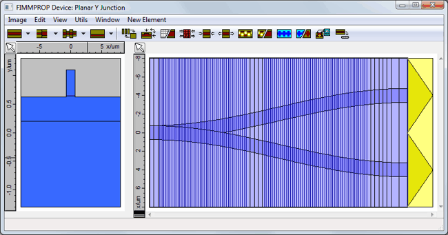
The structure was then discretised along the z-direction by FIMMPROP's taper algorithm. The algorithm does not rely on a grid size; instead it chooses the z-discretisation based on how quickly the modes are changing along the taper. This allows FIMMPROP to model tapers very efficiently: fine discretisation is only used where needed. You can see the structure with the discretisation lines in the picture below.
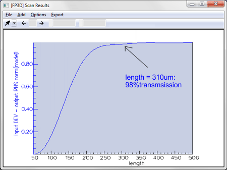
The length of the Y-junction was varied in order to optimise the performance of the structure whilst keeping it as short and compact as possible. FIMMPROP allows you to vary parameters in order to optimise your design very efficiently. For instance, whilst the calculation of the taper itself took 34s, scanning the length of the taper only takes a fraction of this time; in this case just 1.5s per scan point length. This allowed us to plot the study the evolution of transmission with taper length, which is shown in the figure below. This reveals that an adiabatic taper with 98% transmission can be obtained from a taper length of 310um.
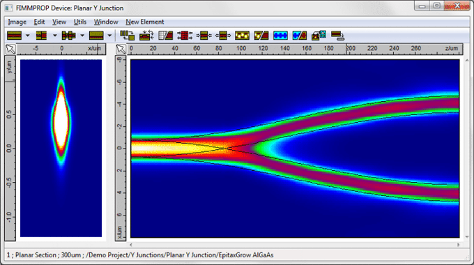
The evolution of the intensity profile along the power splitter for a length of 300um is plotted below.
|

