FIMMWAVEA powerful waveguide mode solver |
    |
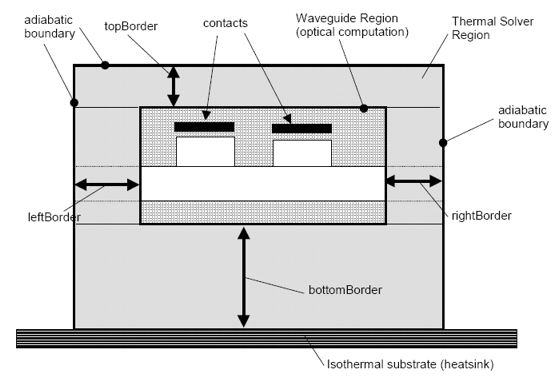
Thermo-Optic SolverSimulating thermo-optic effects in waveguidesThis solver is designed to model the thermal effects in a FIMMWAVE waveguide. It includes a 2D Poisson solver to calculate the temperature profile through a waveguide structure and the structure may be heated with one or more heated contact placed on top of or within the waveguide, or alternatively by a diffuse source. Click here for an application of the Thermo-Optic Solver. Input SpecificationThe module is fully integrated with FIMMWAVE. The thermal properties of a waveguide are defined by assigning a material to each region of the structure. It will then obtain thermal conductivities from the FIMMWAVE material database files. In addition you must define the substrate temperature, the (lateral and vertical) position and dimensions of the heater(s). A heater may be a power source or a temperature source. Temperature dependence of each material may be user-defined in the material database as a polynomial up to 10 terms. The following figure illustrates some of the features of the program. Note that the Thermal Profiler computation can take place in a region much larger than the optical computation.
Output ResultsThe temperature profile is available as In addition, the module will generate a temperature-corrected refractive index profile, which may be directly solved by FIMMWAVE in the usual manner.
CalculationThe calculation is a 2D Poisson Equation solution, using finite differences on an evenly spaced rectangular grid. The even spacing means that very fine details will not be noticed, e.g. a very thin layer of low conductivity. The algorithm assumes that the temperature along the bottom boundary is uniform and known. It further assumes that no heat flows out of the side boundaries - this assumption will be valid provided the width of the modelled region is rather greater than its height. The algorithm also assumes that no heat will flow through the top boundary except in the region of the contact. The algorithm is very fast and takes only a few seconds to calculate a profile, even on a 100x100 grid. The heater is modelled either as a temperature source (even temperature) or a heat source (even heating power per unit area). Design Curve GeneratorThe principle of operation is similar to FIMMWAVE's General Scanners - i.e. the user defines two structures, as a starting structure and an end point structure. The scan proceeds by making a weighted average of the two structures. The scanner can vary one or more of the following parameter during the scan:
The following quantities are calculated during the scan:
Use with FIMMPROP: Thermo-Optic Switch DesignIf you also have FIMMPROP, the Thermo-Optic Module will allow you to model the propagation in a thermo-optic switch – typically a Y junction with heaters placed to induce the light to travel preferably on one branch or the other. The Module and FIMMPROP will work closely together to permit one to study the effects of the heating on the optical propagation.
|


