FIMMWAVEA powerful waveguide mode solver |
    |
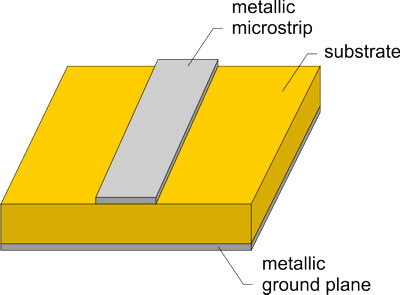
Microwave Modes of a Microstrip LineSimulation with FIMMWAVE softwareFIMMWAVE can calculate the modes of microwave waveguides such as metallic microstrip line waveguides. In this example, the modes of various microstrip lines are calculated with FIMMWAVE's mode solvers for frequencies ranging from 1 to 20GHz. The geometry of the microstrip line is shown below.
The modes of the structure were calculated for three different kinds of substrate: alumina, gallium-arsenide and silicon. The dimensions of the structure are given in the following table.
Parameters of the microstrip line The Ex (horizontal) and Ey (vertical) field profiles for the alumina waveguide at 1GHz are shown below.
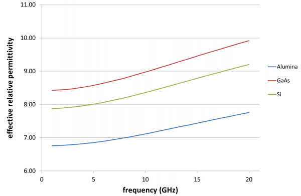
FIMMWAVE allows you to characterise the dispersion of the structure, and the evolution of the effective permittivity for the fundamental mode of the microstrip with frequency is plotted below. The data matches published values with very good accuracy [1].
Reference[1] S. K. Sable, P. Gour, "Dispersion Analysis of a Microstrip Line at Higher Frequencies by using Sonnet and Matlab", 2011 International Confernece on Communication Systems and Network Technologies More publicationsClick here to find publications that include FIMMWAVE simulations of microwave waveguides on Google Scholar.
|


