FIMMWAVEA powerful waveguide mode solver |
    |
Bend Modes & Bend Losses of Optical WaveguidesSimulation with FIMMWAVE softwareFIMMWAVE supports no less than three different bend mode solvers, allowing you to calculate the bend modes of curved waveguides of arbitrary geometries with great accuracy. FIMMWAVE can calculate bend losses accurately.
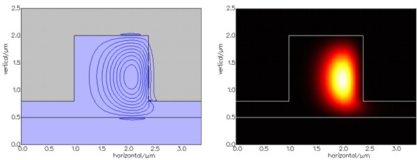
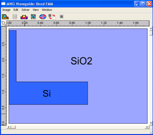
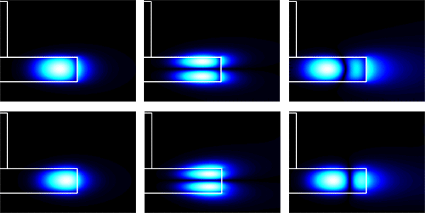
Bend modes of a Planar SOI Waveguide Bend Modes of a Planar SOI WaveguideFIMMWAVE can calculate the bend modes of a planar SOI waveguide in a rigorous way. The FMM Solver used as a bend mode solver relies on fully cylindrical coordinates. Bend losses were calculated with true transparent boundary conditions, which provide more stable and accurate results than PMLs (Perfectly Matching Layers). A low bending loss SOI waveguide was simulated with FIMMWAVE (see details of structure here). The low bending loss was achieved using a large etch depth (r=0.2). For a bend radius of 10um, FIMMWAVE calculated bend losses of 0.00017cm-1 for the fundamental TM-like mode and 6.55cm-1 for the fundamental TE-like mode. The mode profiles below clearly show the field profile distortion associated with the curvature.
The evolution of mode loss with radius of curvature can be generated automatically with a WG Scanner. The resulting curve for the TE-like mode is shown below.
Whispering Cavity Modes of a Microdisk ResonatorHere the FDM Bend Solver was used to calculate the fundamental and high-order bend modes of a silicon mesa disk buried in a silica substrate. The whispering cavity modes were found very easily even for a disk radius as small as 1.49um.
Bend Modes of a Photonic Crystal FibreThe FEM Solver was used as a bend solver to find the bend modes of the same photonic crystal fibre for a radius of curvature of 100um (see the details of the structure here). Bend loss was calculated using PMLs (Perfectly Matching Layers). The contour plots of the fundamental TE-like mode for the straight and the bent PCFs are shown below. You can observe the horizontal asymmetry of the bend mode profile.
More publicationsClick here to find publications that include FIMMWAVE simulations of bends on Google Scholar.
|


