CrystalWaveA powerful photonic crystal simulator |
    |
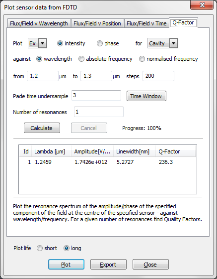
Q-Factor a Photonic Crystal CavitySimulation of a photonic crystal cavity with CrystalWave's FDTDCharacterising an optical cavity with a high Q-factor can be challenging when using a time-domain engine such as FDTD, as these are usually associated with very long calculation times. Our FDTD Engine features an advanced Q-factor Calculator which will allow you to model even the highest Q-factors in a fraction of the time it would take with a conventional FDTD. The Q-factor CalculatorThe conventional approach to obtain the spectral data for a resonant cavity after an FDTD is to perform a Fourier transform on the time-domain data. With this approach it is necessary to run the simulation for long enough to ensure that most of the light has disappeared from the cavity. This can be problematic when characterising cavities with a high Q-factors, as light will decay from the cavity at a very slow rate, leading to very large calculation times. Our Q-factor Calculator allows you to calculate resonant frequencies and Q-factors based on a much shorter durations. Compared with a Fourier transform, it will allow you to obtain the same level of accuracy whilst running the FDTD calculation for less than 25% of the duration.
Modelling a photonic crystal cavityWe will use the Q-factor Calculator to characterise a photonic crystal cavity formed by a single lattice defect, which we designed using CrystalWave. The photonic crystal is etched in a thin membrane of active material (InP); the membrane is 280nm thick and surrounded by air on both sides. The cavity is created in the membrane by removing a single hole.
Light is initially injected in the cavity in the form of a pulse emitted by a dipole, polarised in the plane of the cavity. The excitor is set up so as to excite wavelengths between 1.0 and 2.0um. Using a grid spacing of 20nm we run a 3D FDTD calculation of duration 3000fs, by which time the power in the resonant mode has decayed by a factor 1e-7. We then calculated the spectrum of the light in the cavity using:
In each case we excluded the first 50fs from the time-domain data, as this would have included the initial broadband pulse. The calculation revealed that the cavity supported a single resonance in the range of wavelength that we excited. Both the Fourier transform and the Q-factor Calculator agreed on a resonant wavelength of 1.246um and a Q-factor of 240. You can see the resonance in the plot below, showing flux versus wavelength inside the cavity; this plot was obtained with the Fourier transform.
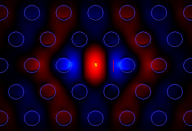
You can see the field profile distribution of the resonance in the plot below.
Using the Q-factor Calculator to reduce calculation timeWe varied the duration of the FDTD calculation in order to study the effect of the duration on the Q-factor calculated with each method. For the Fourier transform calculations we used zero-padding to extend the time-domain window used in the Fourier transform to 20ps; this allowed us to keep a constant resolution for the frequency-domain data. The results are shown in the plot below, which shows relative error on the Q-factor versus duration of the FDTD calculation. From this plot it is very clear that the Q-factor Calculator allows us to calculate resonances using a much smaller FDTD duration than the conventional Fourier transform approach: the Q-factor Calculator only needs a duration of 300fs to obtain a precision below 1% on the value of the Q-factor, whilst the Fourier transform needs 2000fs to obtain the same precision: a reduction of 85% in calculation time!
Further simulationsCrystalWave's Active FDTD module was used to simulate a photonic crystal laser based on the same cavity design.
|


